|
|
|
Beschreibung
|

|
|
|
|
|
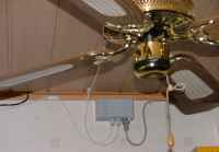
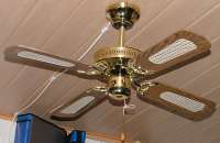
Dies ist eine Erweiterung des Projektes
"Deckenventilator". Die Fernbedienung
per Funk und die erweiterten Drehzahlbereiche
waren schon eine tolle Verbesserung, allerdings
hatte auch diese Steuerung noch einige Schwächen:
- Probleme bei der Anzeige der Drehzahlstufe
bedingt durch Einstrahlung in das lange
Kabel
- Der Ventilator läuft erst in Stufe
3 an
- Schläft man unter dem Ventilator
ein, läuft er die ganze Nacht durch,
am nächsten morgen ist man erkältet
|
|
|
Um diese Probleme zu beheben wurde das
Projekt folgendermaßen erweitert:
- Serielle RS232-Schnittstelle für
die Kommunikation zwischen Haupt- und
Bedieneinheit, dies bedingt auch in
der Bedieneinheit einen Controller
- Aus dem Stillstand wird der Ventilator
in Stufe 3 gestartet
- Eine Timer-Funktion, die den Ventilator
nach einer bestimmten Zeit abschaltet
muss her.
|
|
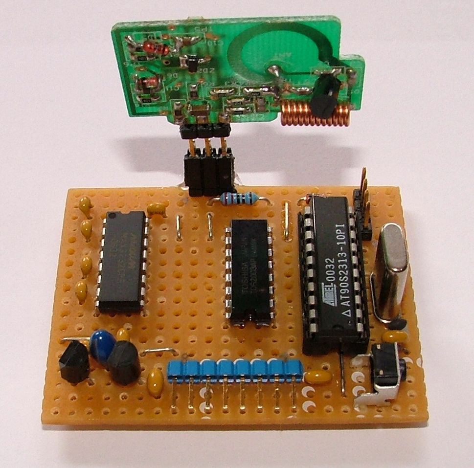
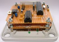
Das MC-Modul der Haupteinheit musste
neu entworfen und um einen MAX232 zum Treiben
der Schnittstelle erweitert werden. Da im Kabel
nun weniger Adern benötigt werden, konnte
auch ein kleinerer Stecker dafür verwendet
werden, wodurch der Platz für den Treiberbaustein
frei wurde. Auf der Platine war auch noch
Platz für einen Taster, mit dem der Lern-Modus
für den Code der Fernbedienung aktiviert
werden kann. Somit kann die Steuerung auch
ohne Bedieneinheit verwendet werden. Der
verwendete AT90S2313 blieb erhalten, die
Software musste natürlich neu geschrieben
werden.
|

|
|
|
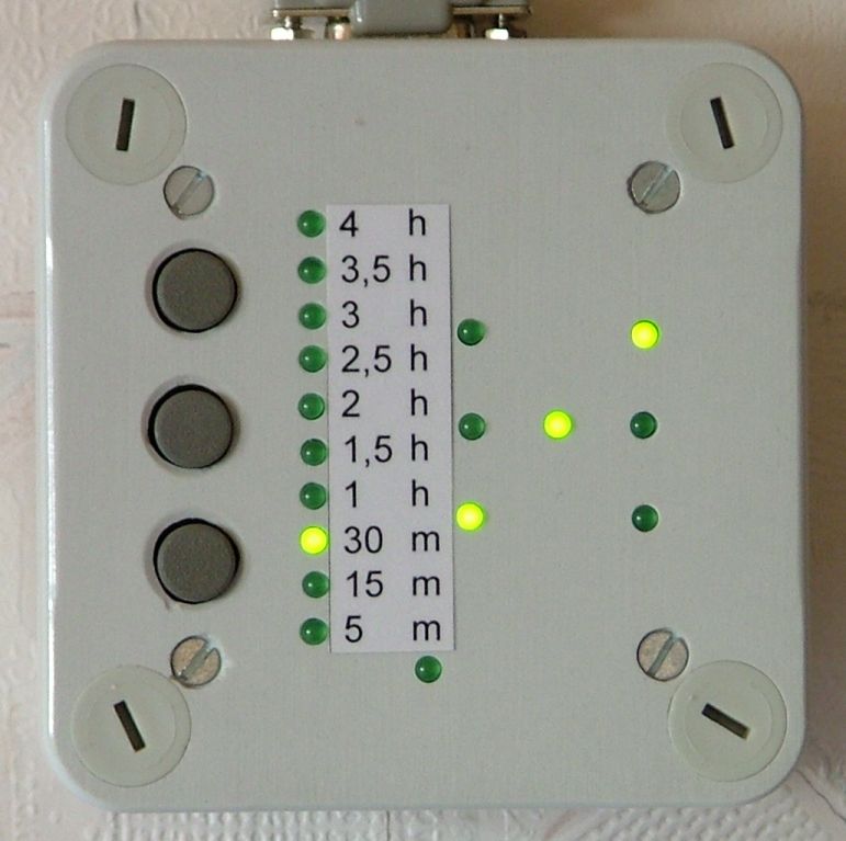
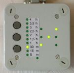
Die Bedieneiheit wurde um 10 LEDs erweitert,
welche die aktuelle Timer-Stufe anzeigen.
Die Anzeige der Geschwindigkeitsstufe
erfolgt nach wie vor durch die als Würfelaugen
angeordneten LEDs
|
|
|
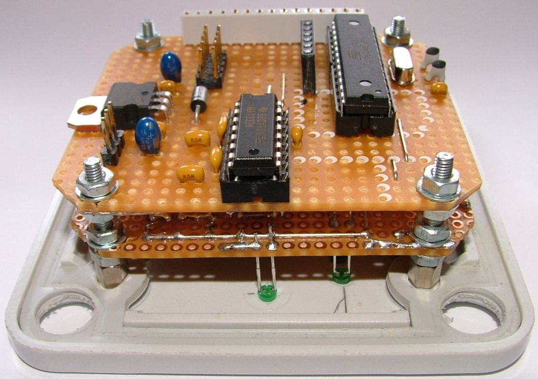
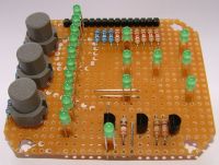
Die Platine in der Bedieneinheit musste
komplett neu entworfen werden. Als
Controller wurde ein ATMega8 verwendet.
Da durch die LEDs auf einer Platine nicht
genügend Platz war, wurden Controller und
Schnittstelle auf einer zweiten Platine
untergebracht, die Huckepack auf der LED-Platine
sitzt. Da der ATMega8 nicht genug Pins besitzt
um jede LED einzeln ansteuern zu können,
wurde dazu eine Ansteuer-Matrix verwendet.
|
|
|
|
Die Timer-Stufe wird immer mit einer
einzelnen LED angezeigt. Die Restlaufzeit
liegt dabei immer zwischen der Zeit an der
leuchtenden LED und der Stufe darunter.
Leuchtet z.B. die LED bei 1h beträgt die
Restzeit zwischen 1h und 30 Minuten. Sinkt
die Restzeit unter 30 Minuten leuchtet die
30min. LED. Ist die letzte Stufe abgelaufen,
wird der Ventilator abgeschaltet.
|
|
Geschwindigkeit ändern:
Taste
+ oder Taste - kurz drücken erhöht bzw.
verringert die Stufe. Wird aus Stufe 0 (Stillstand)
die Taste + gedruckt startet der Ventilator
in Stufe 3 um den Anlauf sicher zu stellen.
Timer-Stufe ändern:
Taste
+ oder Taste - mindestens 2 Sekunden halten
erhöht bzw. verringert die Timer-Stufe alle
0.5 Sekunden um eine Stufe. Befindet sich
beim Halten von Taste + der Ventilator in
Stufe 0 (Stillstand) wird er in Stufe 3
gestartet um den sicheren Anlauf zu gewährleisten.
Wird
Taste - ohne aktivierten Timer gehalten,
wird der Ventilator abgeschaltet.
Nachtmodus:
An der Bedieneinheit
die Modus-Taste (unterste Taste) drücken,
die Anzeigen erlöschen nach einigen Sekunden.
Bei einer Zustandsänderung leuchten die
Anzeigen wieder für einige Sekunden und
erlöschen dann wieder.
Lernmodus:
Taste + und - an
der Bedieneinheit für mindestens 2 Sekunden
gedrückt halten. Die mittlere LED des Würfels
beginnt zu blinken. Nun die Tasten + und
- an der Fernbedienung mindestens 2 Sekunden
gedrückt halten. Beim Loslassen wird ein
neuer Code übertragen. Wurde dieser vom
Controller richtig empfangen stoppt das
Blinken der LED. Diese Tasten können jetzt
zum Steuern des Ventilators verwendet werden.
Der Controller kann bis zu acht Codes gleichzeitig
lernen, genau wie die original Empfänger.
|
|
|
Die Software für beide Controller ist in Assembler mit dem
von Atmel frei verfügbaren AVR-Studio geschrieben.
Die
Kommunikation zwischen den beiden Controllern
ist auf das nötigste beschränkt. Das Hauptmodul
sendet alle zwei Sekunden oder bei einer
Zustandsänderung ein Statusbyte an die Bedieneinheit.
In diesem Statusbyte ist die aktuelle Geschwindigkeitsstufe
(Bit 0..2), Zustand des Lernmodus (Bit 4)
und die Information zum Erhöhen und verringern
der Timer-Stufe über die Fernbedienung (Bit
5 und 6) enthalten. Zur Kennzeichnung des
Statusbyte sind die freien Bits 3 und 7
fest auf 0 und 1.
Bei einer Bedienung über die Bedieneiheit
sendet diese ein Steuerbyte an das Haupt-Modul.
Dabei wird mit gesetztem Bit 0 der Ventilator
gestartet (Stufe 3 wenn in Stufe 0) und mit
Bit 1 gestoppt. Ist Bit 4 gesetzt soll der
Lernmodus gestartet werden. Bit 5 erhöht
die Geschwindigkeitsstufe, Bit 6 verringert
diese. Zur Kennzeichnung des Steuerbytes
sind die Bits 3 und 7 fest auf 1 und 0 gesetzt.
Der Timer läuft im Controller der Bedieneinheit
ab. Ist der Timer abgelaufen wird ein "Stop"
an das Hauptmodul gesendet. Wird der Timer
gestartet, wird ein "Start" gesendet.
Die Anzeige über die LEDs wird mangels genügender
Pins des ATMega8 gemultiplext. Die LEDs
sind in drei Gruppen mit bis zu jeweils
8 LEDs aufgeteilt. Diese werden nacheinander
im 300Hz-Takt durchgeschaltet. Dies ergibt
dann für jede LED-Gruppe eine Schaltfrequenz
von 100Hz mit 33% Duty-Cycle. Der Strom der
LEDs ist daher entsprechend höher eingestellt.
Die Geschwindigkeitseinstellung ist wie
gehabt im Controller des Hauptmoduls untergebracht.
Durch diese Aufteilung kann das Hauptmodul
auch ohne die Bedieneinheit verwendet werden.
|
|
Description
|

|
|
|
This is an extension of the project "Ceiling-Fan".
The radio control and the extension of the
speed range was already a big improvement
but this control had some lacks:
- problems with the display of the
speed step caused by influences to the
long cable
- the fan only starts moving in
stage 3 or higher
- if you fall asleep beneath the fan
it runns the whole night, the next morning
you may have a cold
|
|
|
To resolve these problems the project
was extented the following way:
- serial RS232 interface for
communication between the main module
and the "wall-control", this
requires a controller in the "wall-control"
- from idleness the fan is started
in stage 3
- a timer function which stops the
fan after some time has to be implemented.
|
|
The controller module of the main unit
had to be re-designed and extended with
a MAX323 to drive the interface. Because
there are now needed less wires as before
in the cable, a smaller connector could
be used for this. This gave the space for
the driver device. There was also enough
space for a little push-button which is
used to enter the learn-mode. Because of
this, the main unit can be used also without
the "wall-control". The previously
used AT90S2313 stayed the same, the software
had to be rewritten though.
|
|
|
|
The "wall-controll" was expanded
by 10 LEDs which display the current timer-stage.
The
speed-stage is stillt displayed by the LEDs
placed as dice.
|
|
The board of the "wall-controll"
had to be re-designed completely. A ATMega8
is used as controller. Because of the LEDs
there was not enough space on the board
to hold the controller and interface devices.
This devices where placed on a piggy-back
board. Because the ATMega8 had not enough
pins to drive every LED directly, the
LEDs are driven by a matrix-circuit.
|
|
|
|
The timer-stage is always displayed by
one single LED. The remaining time is always
between the time at the glowing LED and
the next lower stage. For example, if the
1h-LED is glowing, the remaining time is
between 30 minutes and 1 hour. If the remaining
time drops under 30 minutes the 30m-LED
starts glowing. If the time is expired the
fan will be stopped.
|
|
Change speed stage:
Pressing
key + or key - for a short time increases
or decreases the stage. If key + is pressed
from stage 0 (idle) the fan is started in
stage 3 to ensure correct start-up.
Change timer stage:
Holding
key + or key - for at least two seconds
increases or decreases the timer stage all
0.5 seconds. If the fan is in speed stage
0 (idle) the fan is started in speed stage
3 to ensure correct start-up.
Holding
the key - without activated timer stops
the fan immediately.
Night-mode:
Pressing the mode-key
(bottom key) on the "wall-controll"
enters or leaves the night-mode. In this
mode the LEDs go off after some seconds.
If there is a change in the state the LEDs
glow again some seconds and go off again.
Learn-mode:
Holding the + and
the - key on the "wall-control"
for at least two seconds enters the learn-mode.
The midle LED of the dice beginns to blink.
Now the + and - keys on the radio control
must be holded for at least two seconds.
When releasing this keys a new code is transmitted.
If this code is received correctly by the
controller the LED stops blinking. Now this
keys on the radio control can be used to
control the fan. The controller is able
to learn up to eight codes, like the original
receivers.
|
The software is made in assembler with
the free available AVR-Studio from Atmel.
The
communication between the two controller is limited
to the absolutely necessary. The main unit sends every
two seconds a State-Byte to the "wall-control".
The State-Byte contains the current speed stage
(bit 0..2), the state of the learn-mode (bit 4) and
the information for increasing and decreasing the timer
stage via the radio control (bit 5 and 6). To designate
the State-Byte the unused bits 3 and 7 are set to 0
and 1.
Operating the "wall-control" sends a Control-Byte
to the main-unit. Within this the fan gets started with
a set bit 0 (stage 3 if the fan is idle) and stopped
with a set bit 1. When bit 4 is set the learn-mode should
be entered. Bit 5 increases, bit 6 decreases the speed
stage. To designate the Control-Byte bits 3 and 7 are
set to 1 and 0.
The timer runns in the controller of the "wall-control".
When the timer is expired a "stop" is
sent to the main-unit. If the timer is startet, a "start"
is send. Because the ATMega8 has not enough pins the
LEDs are multiplexed. The LEDs get switched with a 300Hz
cycle. This gives a switch frequency of 100Hz with a
duty-cycle of 33% for each group of LEDs. The current
of the LEDs is set higher accordingly.
The speed control is still placed in the controller
of the main-unit. Because of this breakup the main-unit
can be used without the "wall-control".
|
Downloads
|

|
|
|

|
Schaltbild und Layout MC-Modul der Haupt-Einheit
Schematics
and layout of controller board from main-unit
|
|
|
Schaltbild und Layout Wandbedienung
Schematics
and layout of
"wall-control"
|
|

|
Assembler Source Code Haupt-Modul (AT90S2313)
Assembler source code
main-unit (AT90S2313)
|
|
|
Assembler Source Code Bedieneinheit (ATMega8)
Assembler source code
"wall-control" (ATMega8)
|
|
|
|

Copyright(c) 2007 Raabinaror. Alle Rechte vorbehalten.
raabinator_at_web.de
|