|
|
|
Beschreibung
|

|
|
|
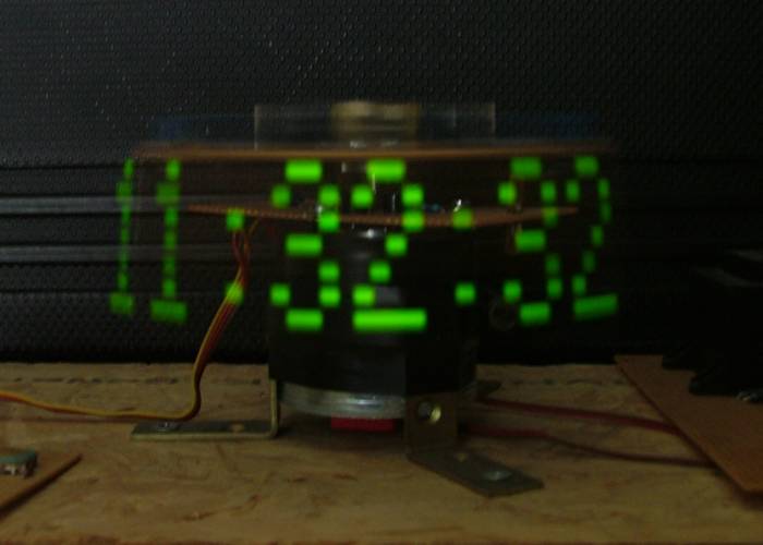
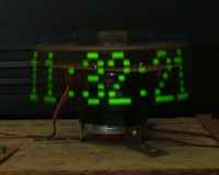
Dies ist eine Uhr die nicht wie üblich
aus vielen einzelnen Segmenten zur Anzeige
besteht. Vielmehr besteht sie aus genau
8 untereinander angeordneten LEDs. Die Trägheit des menschlichen
Auges lässt
bei
Rotation der LEDs ein Eindruck von einem
stehenden Bild entstehen. Dazu muss während
der Rotation an der richtigen Stelle das
dargestellte Muster geändert werden.
|
|
|
|
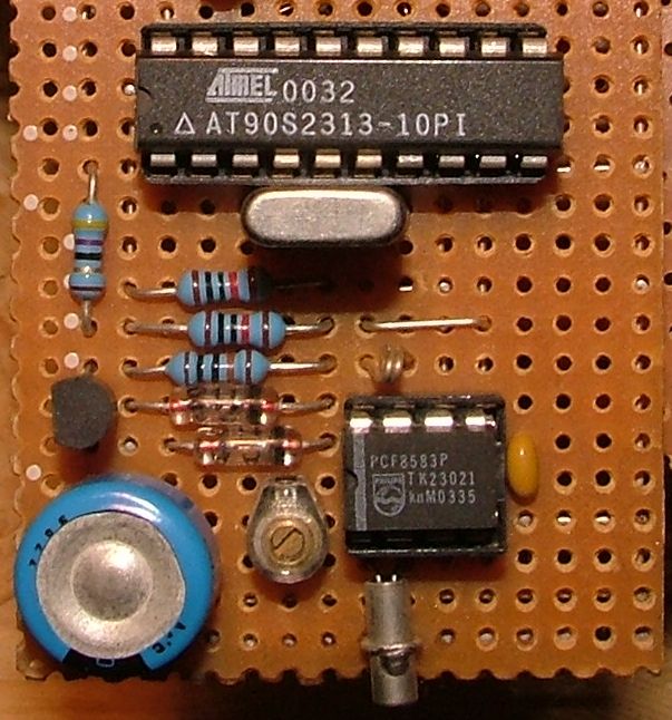
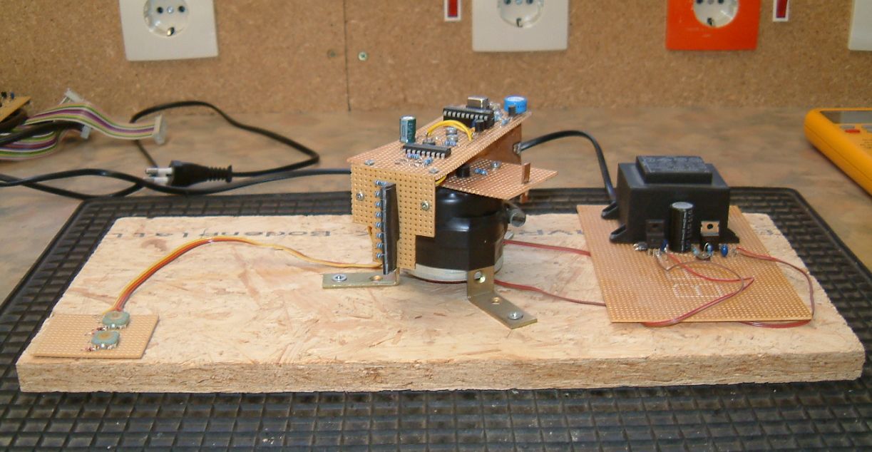
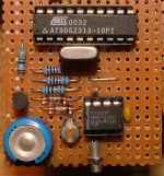
Diese Aufgabe übernimmt ein AT90S2313
Mikrocontroller von Atmel. Für die Uhr wird
ein I²C Echtzeit Uhren-IC von Philips, ein
PCF8583, verwendet. Als Puffer für die Versorgung
des IC wird ein Goldcap mit einer Kapazität
von 0.22F verwendet. Dessen Ladung genügt
um die Uhr für knapp 2 Wochen zu puffern.
Somit kann die Uhr auch getrost mal ausgeschaltet
werden wenn man etwas Ruhe braucht, ohne
dass die Uhrzeit verloren geht.
|
|
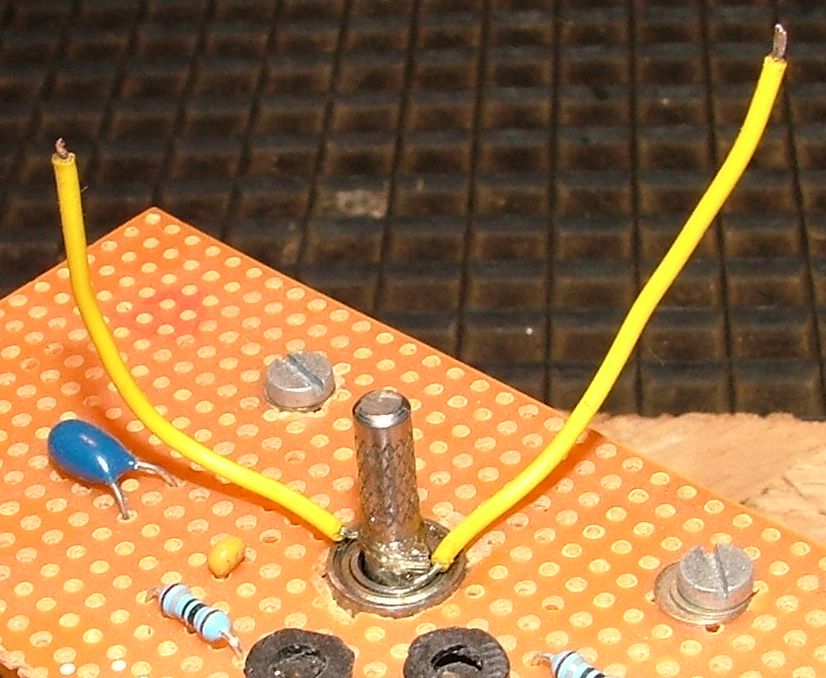
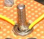
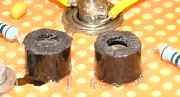
Angetrieben wird die Uhr von eimen Gleichstrommotor
der aus einem alten Grundig VHS Videorecorder
ausgebaut wurde. Die Versorgung für das
rotierende Modul wird über die Welle des
Motors, Masse, und über ein isoliert montiertes
Kugellager aus
Metall übertragen. An diesem Kugellager
sind dazu an der inneren Hülse Kabel angelötet
worden die die Spannung auf die rotierende
Platine Übertragen. Die äussere Hülse ist
möglichst eben in die untere Platine
eingelötet. Dadurch sollen Bewegungen von
den Kabeln währen der Drehung abgehalten
werden damit die Lötstellen nicht brechen.
|
|
|
|
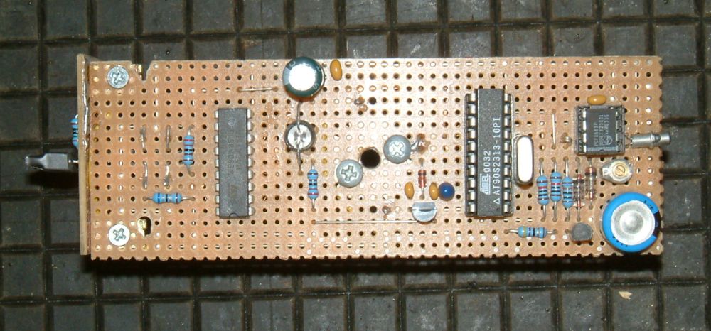
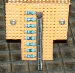
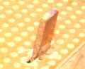
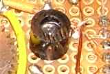
Da der Controller, um ein stabiles Bild
darzustellen, wissen muss an welcher Stelle
sich die LEDs befinden und wie schnell sie
sich bewegen, ist auf der unteren Platine
senkrecht ein kleines Stück Platine als
Index-Markierung eingelötet.
|
|
Das Gegenstück dazu ist eine Gabellichtschranke.
Sie ist auf der Unterseite der rotierenden
Platine so angebracht, dass sie sich ohne
Berührung über den Index-Streifen
hinwegbewegen kann. Daraus kann der
Controller nun die Geschwindigkeit der Rotation,
über die Dauer des Impulses, sowie die Position
ermitteln.
|
|
|
|
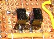
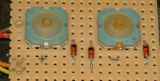
Die Uhr muss auch irgendwie eingestellt
werden. Da man auf der rotierenden Platine
schlecht tasten drücken kann, wird die Information
zum Einstellen optisch von der Grundplatte
übertragen. Dazu sind auf der unteren Platine
zwei Infrarot-LEDs angebracht.
|
|
Das Gegenstück dazu ist ein Infrarot
Fototransistor. Dieser ist so in der rotierenden
Platine eingebaut, dass der sich direkt
über den Sender-LEDs hinwegbewegt. Zum Abschirmen
von Fremdlicht sind Kunststoffhülsen über
Transistor und LEDs angebracht.
|
|
|
|
Angesteuert werden die LEDs über zwei
Tasten. Da zum Einstellen die Information
+ und - ausreichen sind die Tasten über
eine einfache Matrix verschaltet. Bei der
einen Taste leuchtet nur eine LED, bei der
anderen beide. So braucht der MC nur die
Impulse pro Umdrehung zu zählen. Um das
Einstellen zu beschleunigen ist in der Software
eine zwei-stufige Repeat-Funktion integriert.
|
|
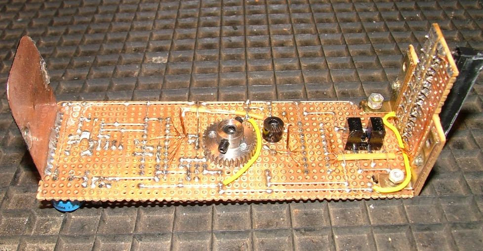
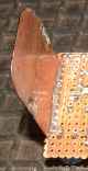
Da Die Platine mit des LEDs etwas schwer
ist und somit starke Vibrationen durch Unwucht auftreten
würden, ist auf der gegenüberliegenden Seite
ein Kupferstreifen als Gegengewicht angebracht.
Damit wird die größte Unwucht ausbalanciert.
Zum Feinabgleich sind auf der Innenseite
Lötzinnklekse aufgebracht. Die Aussenseite
ist schwarz lackiert um bei der Rotation
einen möglichst großen Kontrast zum Licht
der LEDs zu erhalten.
|
|
|
|
Description
|

|
|
|
This is a clock that doesn't consist,
as usual, of many single segments as Display.
Actually it consists of 8 LEDs that are
arranged below each other. The laziness
of the human eyes produces the impression
of an stable picture. Therefore while rotating
the displayed pattern must be altered at
the right position.
|
|
|
|
This is the task of a AT90S2313 microcontroller
from Atmel. For the clock function a IIC
clock circuit from Philips, a PCF8583, is
used. As backup supply for this circuit
a 0.22F Goldcap capacitor is used. The load
of this capacitor is enough to buffer the
time for about two weeks. Therefore the
clock can be switched off without losing
the time if you need a bit of silence.
|
|
The clock is driven by a DC-motor which
is removed of an old Grundig VHS videorecorder.
The supply for the rotating board is led
over the shaft of the motor (ground) and
over a isolated metal ball-bearing. Therefore
at the inner case are soldered two wires
that lead the supply voltage to the rotating
board. The outer case is soldered evenly
in the lower board. This is to reduce vibrations
of the wires and to avoid breaking solder
points.
|
|
|
|
Because the controller needs to know
where the LEDs are and how fast they are
moving to display a stable picture, a part
of a pcb is soldered vertically into the
lower board as an index mark.
|
|
The counterpart for this is a fork light
barrier. It is mounted at the lower side
of the rotating board in a way that it doesn't
touch the index mark while moving over it.
With this the controller can recognize the
speed and the position of the rotation out
of the time and duration of the impulse.
|
|
|
|
Somehow the clock must be adjusted. Because
you can't push buttons on an rotating board
the information to adjust the time is transmitted
optically from the lower board to the rotating
one. Therefore at the lower board are mounted
two infrared LEDs.
|
|
The counterpart for this is a infrared
photo-transistor. This one is monted in
the rotating board in a way that it moves
directly over the transmitter LEDs. To shield
faulty light from the transistor,? plastic
cases are glued at the transistor and
LEDs.
|
|
|
|
The LEDs are controlled by two buttons.
Because it is enough to know the information
'increment' and 'decrenebt' to adjust the
clock the buttons are connected in a simple
matrix. For one button only one LED
is on, for the other button both LEDs are
on. Therefore the controller has only to
count the impulses per rotation. To speed up
the adjustment there ist a two step repeat
function implemented in the software.
|
|
Because the bord with the LEDs is a little
bit heavy, strong vibrations would occur
from the imbalance. Therefore a copper balance
weight is mounted on the opposite side of
the board. This removes the greatest imbalance.
For a fine adjust there are solder points
at the innerside. The outer side of the
copper weight ist painted black to get the
greatest possible contrast with the light
of the LEDs.
|
|
|
|
Weitere Bilder / more pictures
|

|
|
|
|
|
Downloads
|

|
|
|

|
Assembler Source Code
|
|
X
|
Schaltbild wird nachgereicht sobald es
wieder auftaucht
Schematics will be added
when I find them again.
|
|
X
|
Layout wird nachgereicht sobald es wieder
auftaucht
Board layouts will be added
when I find them again.
|
|
|
|

Copyright(c) 2007 Raabinaror. Alle Rechte vorbehalten.
raabinator_at_web.de
|