Deckenventilator/Ceiling Fan


[Prop-Clock][Thermometer][Deckenventilator/Ceiling Fan][Deckenventilator 2/Ceiling Fan 2]
Home 
News 
Software 
Elektronik 
Impressum 
Disclaimer 


Beschreibung deutsch

Description english

Downloads


Beschreibung

Hardware

Dies war einmal ein standard Deckenventilator aus dem Supermarkt. Er hatte eine Schnur-Steuerung mit drei Stufen. Diese Stufen waren mir aber zu grob abgestuft um ihn über Nacht im Schlafzimmer laufen zu lassen. Also habe ich den Ventilator zerlegt und herausgefunden, dass die Geschwindigkeitsumschaltung durch Umschaltung von Kondensatoren (wie üblich) realisiert war. Ich habe dann den Gesamtwert der Kondensatoren in sieben Stufen aufgeteilt, die durch eine Steuerung an die entsprechende Motorwicklung gelegt werden.

Ventilator / fan

Sender / transmitter

Empfänger / receiver

Um etwas mehr Komfort in die Steuerung zu bringen wollte ich sie mit einer bereits vorhanden Funk-Fernbedienung für Funk-Steckdosen aus dem Baumarkt bedienen.

Als ich eine Steckdose zerlegte war zum Glück der HF-Teil auf einer gesonderten Platine untergebracht. Nach Ermittelung der Betriebsspannung des Moduls und Analyse des vom Modul gelieferten Datentelegrammes konnte ich daran gehen eine Steuerungssoftware für den verwendeten AT90S2313 Microcontroller von Atmel zu erstellen.

 HF Modul

Wand-Bedienung

Zusätzlich zur Funk-Steuerung habe ich noch eine Wand-Bedienung realisiert um nicht völlig auf Funk angewiesen zu sein (falls der Sender mal verlegt ist...). An der Wand-Bedienung wird die aktuelle Geschwindigkeitsstufe mittels sieben LEDs als Würfelaugen angezeigt. Für den Betrieb bei Nacht kann die Anzeige in einen Modus gebracht werden, bei dem die LEDs nach einer Zustandsänderung nach 2 Sekunden automatisch abgeschaltet werden.

Da im Fuß des Ventilators nicht genügend Platz für die Steuerung war habe ich sie in einem gesonderten Gehäuse untergebracht. Die Steuerung ist mit einem 4x1.0 mm² Kabel mit dem Ventilator verbunden. Die Wand-Bedienung wird mit dem Grundgerät über ein 10 poliges Datenkabel und 9 poligen Sub-D Steckverbindern verbunden.

 Haupt Gerät

Hauptgerät offen

Der Microcontroller ist auf der kleinen Platine rechts oben untergebracht. Auf dieser Platine ist auch das HF-Modul aufgesteckt. Für besseren Empfang ist das Modul mit seiner Antenne nach vorne ausgerichtet. Auch die Relaistreiber und die Spannungsregler für Digitalteil und HF-Modul sind auf dieser Platine untergebracht.
Die Kondensatorbank mit Relais und Netzteil sind auf der großen Platine in der linken Bildhälfte unrergebracht.

Dieses Bild zeigt das Microcontroller Modul alleine. Es ist mit einer 8 poligen Stiftleiste mit dem Hauptmodul verbunden. Das HF-Modul ist auf eine 3 polige Buchsenleist aufgesteckt. Die Verbindung zur Wand-Steuerung erfolgt über ein 10 poliges Flachbandkabel mit Wannenstecker. Rechts unten sind die beiden Spannungsregler für 9V (HF-Modul) und 5V (Controller) zu sehen.

MC Modul

Hauptmodul

Dieses Bild zeigt das Haupt-Modul. Oben links sind die Kondensatoren zu erkennen. Es sind 3 Bereiche die in 7 Stufen im Binärsystem an die Hilfswicklung des Motors geschaltet werden. Rechts daneben sind die für die Umschaltung nötigen Relais mit den dazugehörigen VDRs zum Schutz der Kontakte zu sehen. Etwas unterhalb der Mitte ist ein sogenanntes Pilot-Relais. In Stufe 0 schaltet es den Motor komplett stromlos. Darunter ist noch das Netzteil mit Netzfilter und Sicherung zu sehen.

Dieses Bild zeigt das Wand-Bedienungs/Anzeige Modul. Das Ganze ist in einer Aufputz-Verteilerdose aus dem Baumarkt untergebracht. Die Verbindung zum Hauptmodul wird über ein 10 poliges Datenkabel mit 9 poligen Sub-D Steckverbindern hergestellt.

Wandsteuerung innen

warning

Achtung!

In diesem Projekt wird mit Netzspannung gearbeitet. Bei Berührung mit Netzspannung besteht Lebensgefahr. Beim Nachbau müssen unbedingt alle Sicherheitsvorkehrungen betreffend Netzspannung getroffen und eingehalten werden. Es muss mit grösster Sorgfart gearbeitet werden!

Software

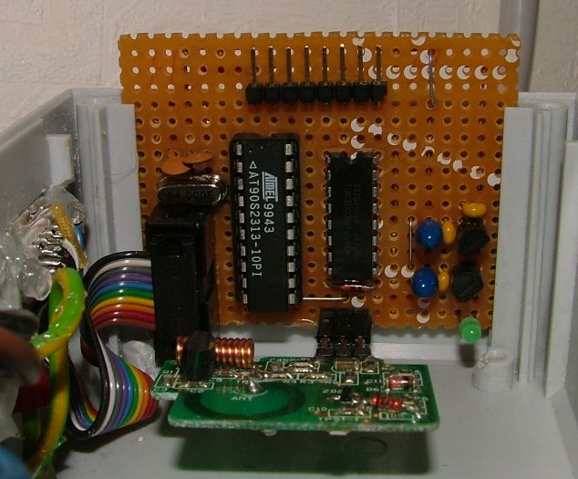
Die Software ist in Assembler mit dem von Atmel frei verfügbaren AVR-Studio geschrieben.
Die 
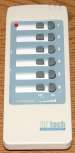
Stufen werden mit den Tasten + und - der Funk- oder Wand-Bedienung erhöht bzw. verringert. Zwischen zwei Stufen ist dabei eine Verzögerung von 200ms eingebaut, einerseits zum Entprellen der Tasten und andererseits um bei festgehaltener Taste an der Funk-Bedienung nicht zu schnell durch die Stufen zu schalten.
Mit der 3. Taste der Wand-Bedienung kann zwischen dem normalen Anzeigemodus und dem Nachtmodus 
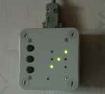
gewechselt werden. Im Nachtmodus wird die aktuelle Stufe nach der Änderung nur für ein paar Sekunden angezeigt und die Anzeige danach dunkel geschaltet.

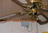
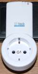
Der Empfänger kann wie die original Steckdosen Funk-Steuerung auch eine neue Taste 'lernen'. Dazu werden an der Wand-Steuerung die + und - Tasten gleichzeitig gedrückt bis die Lern-LED leuchtet. Nun werden die + und - Tasten des Senders für mindesten 2 Sekunden gedrückt. Beim Loslassen der Tasten des Senders wird eine neue Codierung für diese Tasten übertragen. Diese merkt sich der Empfänger im EEP und reagiert künftig nur noch auf diesen Code.  


Description

Hardware

This was once a standard ceiling fan from the supermarket. It had a cord control with three speed stages. This stages seemed too coarse to me to let it run overnights in the sleeping room. Therefor I demounted it and found out, that the speed setting is realized through switching capacitors at an motor coil (traditional speed setting of an AC motor). I divided the total capacitance value into seven steps which are put to the coil via an electronic control.

fan

transmitter

receiver

To put more comfort into the new controller I wanted to control the fan with a radio remote control from a radio controlled ac-mains socket I bought in the hardware store.

When I decomposed the socket I realized that the rf-part was put on a separate module. After analyzing the power supply and the supplied data telegram of the module I was able to write a software for the used AT90S2313 controller from Atmel.

 radio module

wall control

Additionally to the radio control I realized a kind of "wall-control", because to be not only dependent on the radio control (maybe this could be displaced...). The "wall-control" displays the actual speed with seven LEDs that are arranged like eyes on a dice. For operation at nights the display can be set in a mode where it switches off the LEDs after two seconds after the step value chanched.

Because in the base of the fan wasn't enough space for the new control I put it into a separate housing. The control is connected with the fan via a 4x1.0mm² cable. The wall-control is connected with the main unit via a 10 wire data cable and 9 pin sub-d connectors.

 main control unit

main unit open

The microcontroller is located on the short board in the upper right. On this board is also plugged the rf-module For better reception of the rf signal the module is dircted with the antenna to the front of the housing. Moreover the relais drivers and the voltage regulators for the digital part and the rf module are placed on this board.
The capacitor bank with relais and the mains power supply are located on the left half of the picture.

This picture shows the microcontroller module alone. It is connected with a 8 pin connector with the main board. The rf module is connected with a 3 pin connector. The connection to the wall-control is made with a ribbon cable and 10 pin connectors. In the lower right you can see the voltage regulators for the 9V (rf-module) and the 5V (controller) supplies.

mc module

main module

This picture shows the main module. In the upper left you can see the capacitors. There are 3 ranges that are switched in 7 steps in the binary system to the motor coil. Right of this there are the needed relais with the  VDRs that protect the contacts. A little bit below the middle you can see a so called pilot relais. In step zero ist disconnects the motor completely from the mains supply. Below that there is the main supply with mains filter and the fuse.

This picture shows theinner of the "wall-control/display" module. It is placed in a electricity distribution box from the hardware store. The connection to the main unit is made via a 10 wire data cable with 9 pin sub-d connectors.

hand unit module

warning

Caution!

In this project mains power is used. When touching this voltage you can risk a electric shock. When rebuilding this you must pay attention to all security precautions belonging to mains power. Work with greatest care ant attention!

Software

The software is made in assembler with the free available AVR-Studio from Atmel.
The speed is increased and decreased with the '+' and '-' keys on the radio remote control or the wall-control. Between two steps is a delay of 200ms to debounce the keys and to slow down the speed change when holding down a key on the radio remote control.
With the third key at the wall control you can change between the normal display mode and the night mode. In the night mode the actual step is only displayed for two seconds after a speed change. After that the display is switched dark.

Like the original rf-sockets the controller can learn a new key of the remote control. Therefore the '+' and '-' keys on the wall-control must be hold down for at least two seconds. A LED on the wall-control signals the learn state. Now you must hold down the desired key pair on the radio remote control for at least two seconds. When you release the keys a new code for this keys is transmitted to the receiver. The receiver recognizes this code and stores it in the EEP. In the future it only reacts on this code.


Downloads

 PDF

Schaltbild Haupt- und MC-Modul
Schematics main and controller unit

 PDF

Layout Haupt- und MC-Modul
Layout main an controller unit

 PDF

Schaltbild Wandbedienung
Schematics wall-control

 assembler source

Assembler Source Code


Copyright(c) 2007 Raabinaror. Alle Rechte vorbehalten.
raabinator_at_web.de